Mechanical Engineering · Robotics & Space Systems

Gabriel
Lima

I build things that move on their own and survive harsh environments, from autonomous race cars to rocket payloads.

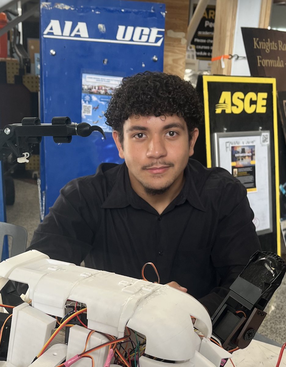
Portrait of Gabriel Lima
SchoolUniv. of Central Florida
DegreeB.S. Mechanical Eng.
MinorIntelligent Robotic Systems
CADCSWA · CSWP · CSWP-DT
SeekingInternships in robotics, autonomy & aerospace hardware
1st

Place, UCF AI Racer Grand Prix 2026, with a record top speed

−23%

Average collision rate after suspension tuning on F1TENTH cars

31g

Sustained-load test level set for an IREC 2027 rocket payload

−52%

Tail servo holding torque on a robotic scorpion (4.37 → 2.1 kg·cm)

Projects

5 sheets
01

AI Racer Grand Prix: 1st Place

Mechanical / Electrical Engineer · Team SHPE UCF
Jan – May 2026

Small-scale autonomous F1-style car running a Linux, ROS 2 driving stack. Our team worked across mechanical, electrical and software groups and took first place at UCF's AI Racer Grand Prix with a record top speed.

  • Modeled the chassis, suspension, steering, front and rear wings, and bumper in SolidWorks, then prototyped and finalized them in ABS on a Bambu Lab printer.
  • Raised top speed from 8 to 10 m/s by removing the rear wing and downsizing the chassis to cut dead weight and battery strain.
  • Designed a compact mounting system for the Raspberry Pi 4 and RPLIDAR inside competition size limits, and helped wire and solder the onboard electronics.
SolidWorksROS 23D printing (ABS)Raspberry Pi 4RPLIDARSoldering
02

Autonomous Driving Research

Research Assistant · CAVREL Lab, UCF
Oct 2026 – Now

Developing and testing ROS 2 autonomy software on 1/10-scale F1TENTH race vehicles for local and international autonomous racing competitions.

  • Restored accurate odometry for SLAM by tracing a sign bug in the VESC driver's Ackermann kinematic model that flipped the car's heading by 180°, then validated the fix with controlled drive tests.
  • Tuned a reactive gap-following steering controller to hold sharp S-turns and wide turns at up to 4 m/s by adjusting proportional gain, smoothing, saturation limits and look-ahead range.
  • Cut the average collision rate by 23% across test runs by tuning suspension on several F1TENTH vehicles, and diagnosed VESC, power board and LiDAR faults.
STACK · F1TENTH Powerboard · VESC motor controller · Hokuyo UST-10LX LiDAR · NVIDIA Jetson · 3S LiPo · ROS 2 · SLAM · Follow-the-Gap
ROS 2LinuxPythonSLAMVehicle kinematicsControls tuningHardware debugging
03

IREC 2027 Rocket Payload Test Campaign

Lead Test Engineer · RocketSHPE (SHPE UCF × Knights Experimental Rocketry)
Sep 2026 – Now

A multi-sensor payload that measures pressure, temperature and acceleration through flight and checks whether a student-designed vibration-isolation mount protects its data logging. I lead the environmental testing: deciding what the payload must survive, writing the procedures and designing low-cost rigs to prove it. The notes below show the full test matrix, the rig math and the pressure test.

  • Set flight-derived test levels and pass/fail criteria: 31 g sustained load, thermal soak to 150°F for a June launch in Midland, TX, and vacuum to 26.5 kPa for apogee near 32,780 ft.
  • Designing a centrifuge (0.25 m arm at 333 rpm gives 31 g, from a = ω²r) and a guided drop rig where drop height sets peak g and pad stiffness sets pulse length, together for about $150.
  • Wrote thermal, static load and vacuum chamber procedures backed by hand calculations of loads, shock pulses and vent sizing.
  • Coordinating with mechanical, electrical and software leads to test the Teensy 4.1, dual KX134 high-g accelerometers, dual MS5611 barometers and microSD logging, including a script that flags missing samples.
Test planningEnvironmental testingHand calcsRig designTeensy 4.1Systems engineering
03-A

Test matrix

Every test level traces back to a real flight condition: the launch site in Midland, TX in mid-June, a predicted apogee near 32,780 ft and the loads from boost, burnout, parachute deployment and landing. Each level carries margin above what we expect in flight, and every test has a written pass/fail rule before it runs.

EnvironmentFlight driverTest levelMethodPass if
Sustained gBoost, about 25 g31 gCentrifuge, payload powered and loggingNothing moves, loosens or cracks; no resets, SD errors or data gaps
ShockBurnout, deployment, landingStep up from 2 cmGuided drop on a carriage; height sets peak g, pad sets pulse length; every axisNothing shifts or unseats, especially the SD card; no resets at impact
Structural loadFull boost load on sled, plates, mounts, battery holderMass × g, 60 s holdStatic weights in thrust direction, then flipped; spares stepped up ~10% to failureNo cracks, no permanent bending, no loose fasteners
Thermal92–95°F Texas ambient, airframe heating, electronics120 → 135 → 150°FLab oven soak, 1 hr per step; load PETG mounts while hot, then re-run drop and static testsMounts hold shape; Teensy temperature, battery voltage and SD write speed stay in limits
PressureApogee near 32,780 ft26.5 kPaVacuum canister pumped down in steps with a reference barometer; measure vent lag on fast releaseBoth MS5611s match the reference and each other; vents keep up; housing intact
Power & dataFull mission on one batteryWhole flightBattery endurance, brownout and reset tests; numbered samples checked by a scriptLogging starts at launch, survives resets and loses no samples
03-B

Low-cost rig design

CONSTRAINT · A student budget rules out renting a commercial centrifuge, shaker or thermal-vacuum chamber, so each rig is built from parts we can buy or borrow.

Centrifuge. Spinning the test item on an arm makes the outward pull act like boost acceleration. With a 0.25 m arm, the target of 31 g sets the speed:

ω = 333 rpm × 2π / 60 = 34.9 rad/s
a = ω² r = 34.9² × 0.25 = 304 m/s² = 31.0 g

The rig uses a 12 V gear motor, a bearing-supported shaft, a counterweight and a plywood enclosure, for about $85–115.

Guided drop. A carriage drops onto a pad. The pad's stiffness sets how long the shock lasts, and the height sets its peak:

h = 2 g² · 9.81 · t² / π²    k = π² m / t²

A 2 cm start height works out to about a 20 g, 5 ms pulse, so the test begins gently and steps up. Cost: $15–50.

03-C

Pressure and vent test

The payload finds altitude from two barometers inside a sealed housing, so the air inside has to keep up with the air outside during a fast climb. If the vents are too small, the readings lag and the housing takes a pressure load it wasn't designed for.

The test puts the powered payload and a phone barometer in a vacuum canister and pumps down through three flight points. At each one, the two MS5611 readings are averaged over 30 s and compared with the phone and with each other. At mid-range, a quick release of the valve shows how long the sensors take to catch up, which measures vent lag directly.

  1. Step 1
    91.6 kPa · Midland ground level, 2,780 ft
  2. Step 2
    ~60 kPa · mid-flight; vent-lag release test here
  3. Step 3
    26.5 kPa · apogee, about 32,780 ft
  4. After
    Slow return to room pressure, then a functional check and the data-gap script
04

Robotic Scorpion Hexapod

Mechanical Engineer · Project STRIDE, UCF STEEL · Tail, claws & chassis design
Sep 2026 – Now

A servo-driven hexapod built as a scorpion so the claws and tail add moving parts beyond a basic walker. On a team of seven, I designed the tail, the claws, the second-story deck and parts of the front body in SolidWorks, all printed in PETG. We built it, drove it and presented it to industry judges at the UCF STEEL Fall 2026 showcase. The design notes below walk through the tail and chassis.

  • Cut tail servo holding torque by 52% (4.37 to 2.1 kg·cm) with moment calculations that set the tail's resting pose, keeping the MG996R inside its continuous rating.
  • Sized the structure to a 2.69 safety factor in a three-leg tripod stance for a predicted 5.3 lb robot, and budgeted power for up to 315 W peak servo draw on a regulated 6 V rail.
  • Built an 18-mode FMEA and brought all six highest-risk failure modes from RPN 32 to 8 or lower with mechanical stops, a control watchdog, output gating at power-up and fused battery power.
SolidWorksMechanical drawingsFMEAMoment calcsESP32MG996R servos3D printing (PETG)
04-A

Tail design

PROBLEM · A 20 in tail held out straight puts a 4.37 kg·cm holding load on its base servo. The MG996R is rated for about 2.5 to 3.0 kg·cm continuous, so a straight tail would overheat the servo and sag over a demo.

I broke the tail into short PETG segments so it could curl. Running the moment calculation for each pose showed that arching the tail upward into an S-curve moves its center of gravity back over the base. That cuts the effective lever arm by more than half, and the holding torque drops to 2.1 kg·cm, inside the servo's safe continuous range.

Not every iteration worked. A chain-link version put too much stress on the small links, and they fractured under load, so the final build went back to the larger segmented design.

  1. Rev A
    First segmented tail. Tail base and linked segment assembly in SolidWorks to prove out the range of motion.
  2. Rev B
    Remodeled segments. New base, two- and three-segment links and a stinger end, plus base and servo platforms that mount the tail to the body.
  3. Rev C
    Chain-link trial. Repeating chain links with a servo-driven first link and guide wheels. The links were under too much stress and fractured, so we dropped this design.
  4. Final
    Back to segments. The built robot uses the Rev B segmented tail, which carries the load without cracking.
04-B

Chassis design

PROBLEM · Nineteen-plus servos, two driver boards, an ESP32, a buck converter and a LiPo all have to fit inside a scorpion-shaped body that still carries a 5.3 lb robot on three legs.

The chassis has two stories. The main body holds the leg servos in pockets along each side. The second-story deck I designed sits above it and carries the servo driver board and the tail servo, so the legs are driven from above with short wire runs. I also designed parts of the front of the body, where the claws mount.

  1. Front
    Front body and claws. Designed sections of the front body and the claws that mount to it.
  2. Deck V3
    Second-story plate. Cutouts and mounting holes for the driver boards and wiring slots.
  3. Deck V4
    Organized wiring. Added dedicated wire slots to keep the servo wiring organized, plus mounts for the servo board and the tail servo.
05

S.A.I.L. CubeSat Mission Design

Mission Designer · Florida Space Institute CubeSat Mission Design Workshop
Summer 2026

Sargassum Analysis & Inter-satellite Laser (S.A.I.L.) is a CubeSat constellation designed for the Florida Department of Environmental Protection. Its main goal is to demonstrate laser crosslinks between small satellites, using live sargassum bloom imagery along Florida's coasts as the data being moved. I designed it with two teammates.

  • Wrote the mission statement, objectives and tiered success criteria: deploy six 6U CubeSats, move data between satellites at 0.6 to 1 Gbps and keep links running for a 100 to 120 day mission.
  • Built data, storage, link, pointing, power and mass budgets: the S-band downlink closes with 16–20 dB of margin against a 6 dB requirement, and both satellite types come in under 7 kg with 25% contingency.
  • Defined CONOPS for observation and relay satellites, operating modes from safe mode to crosslink and downlink, commissioning checkpoints and a $4M to $8M program budget.
Mission designSystems engineeringLink budgetsPower budgetsCONOPSRequirements
05-A

Mission design

CUSTOMER NEED · FDEP wants a cheap way to move large volumes of coastline data. The constellation proves laser crosslinks can do it, using sargassum blooms along Florida's Atlantic and Gulf coasts as live data.

We split the constellation into two satellite types. Observation sats point at the coast during an imaging window, store the images and their own health data, then crosslink to a visible relay. Radio sats catch the crosslink, log how well it performed and downlink everything to the ground over X-band.

Success is tiered so the main goal survives a partial failure:

  1. Minimum
    At least 4 satellites deployed and in contact; a stable crosslink moving 2 GB of observation data per day; link metrics sent to the ground.
  2. Full
    All 6 satellites holding the crosslink for the whole mission at 4 GB or more; FDEP gets regular bloom data and health reports every pass; daily downlinks succeed 90% of the time.
  3. Schedule
    Start Nov 2026, launch by May 2028, six months of operations, with data to the customer by spring 2029.

Each satellite runs Safe, Standby and mission modes. Safe mode kicks in below 30% battery and shuts off payloads and radios, and the laser crosslink runs in three phases: 5 minutes to acquire and track, 120 s at 35 W moving about 12 GB, then 30 s to power down.

05-B

Engineering budgets

Every subsystem choice was checked against a budget before it went in the design.

Downlink margin16–20 dBvs. 6 dB required · S-band 2.23 GHz, 1 W, 1 Mbps, 450 km orbit, 10° elevation, 1,570 km slant range, 5 m ground dish
Pointing error0.006°about 66 m at 600 km, well inside the SCOT20's ±1° fine-steering mirror
Mass6.78 / 6.96 kgobservation / radio sat, including 25% contingency, under the 6U limit
Power25.2 Wrecovered in Standby from dual deployable arrays into a 100 Wh battery; laser peaks at 35 W
StorageOrbit by orbitsimulated over a day so onboard storage fills between passes and clears at each downlink without overflowing
Program cost$4M–$8Mfor six 6U CubeSats, including launch, ground network time and laser terminals

Leadership & Training

Clubs, teaching & workshops

AI Racer

Mechanical Workshop Lead · Oct 2026 – Now

Co-chairing the workshops committee and building the spring mechanical curriculum (chassis, suspension and steering, sensor mounting, 3D printing) so new students can take a bare chassis to a race-ready autonomous car.

SHPE UCF

Project Planning Director

Plans timelines for the chapter's workshop series and competitions. Organized and budgeted a five-week SolidWorks CSWA workshop series, and helped start the SHPE and Florida Space Institute collaboration behind the IREC payload.

UCF SMART Workshop

Cleanroom semiconductor fabrication

Hands-on semiconductor fabrication in UCF's cleanroom. Pursuing UCF's Certificate in Semiconductor Engineering and Manufacturing Instruction.

Skills

Tools & methods

Design

SolidWorks (CSWA, CSWP, CSWP-DT), Onshape, mechanical drawings, design for manufacturing

Fabrication

3D printing (PLA, ABS, PETG), TIG welding, cleanroom processing, soldering, wire bonding

Software

ROS 2, Linux, Python, C, microcontroller integration, motor control

Analysis & test

Test planning, environmental testing, FMEA, hand calculations, load and torque analysis

Languages

English (fluent), Portuguese (intermediate), Spanish (basic)

Revision: open to opportunities

Let's build something that moves.

I'm looking for internships in robotics, autonomy, aerospace hardware and test engineering.

Email
gabelima007@gmail.com
LinkedIn
in/gabriel-lima-4901a23a9
Based in
Orlando, FL